
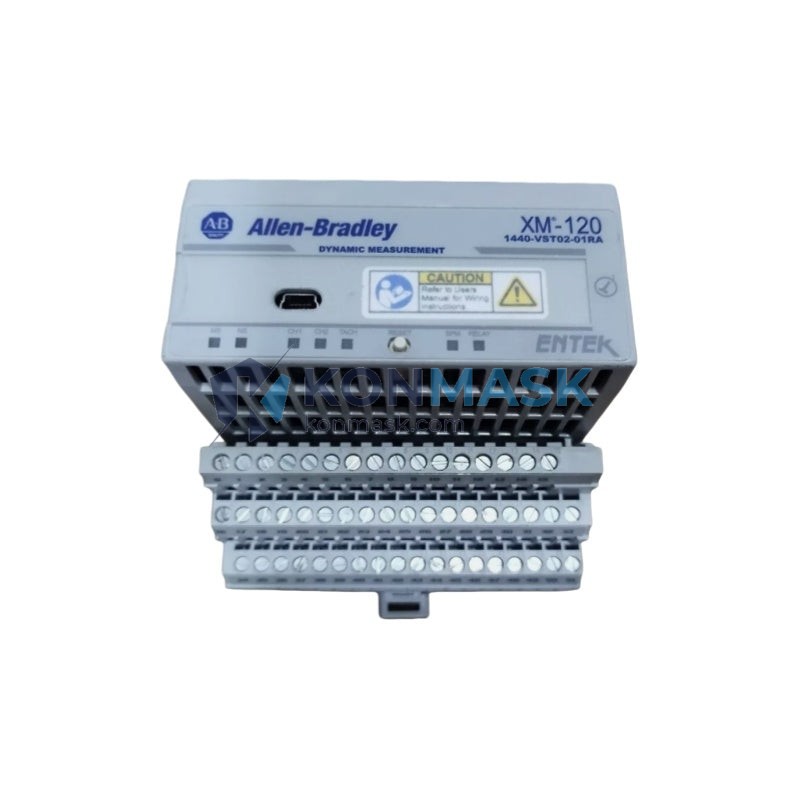
Allen-Bradley 1440-VST02-01RA – Speed & Tachometer Input Dynamic Measurement Module | XM-120 Series
Engineering Background
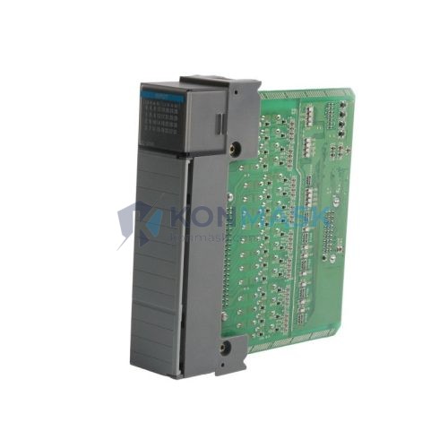
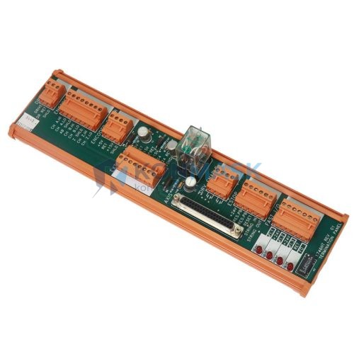
The Allen-Bradley XM-120 (catalog number 1440-VST02-01RA) is a dedicated dynamic measurement module engineered by Rockwell Automation for continuous machinery protection and condition monitoring. Designed to integrate natively within the ControlLogix and GuardLogix control architectures, it delivers real-time speed and tachometer signal acquisition for rotating equipment across heavy industrial environments.
Product Positioning
Targeted at reliability engineers and OEM system integrators, the 1440-VST02-01RA serves as the tachometer reference input node within a distributed XM Series monitoring rack. It provides the rotational speed reference required by companion vibration and process modules, enabling phase-referenced spectral analysis, order tracking, and machinery protection logic within a unified Logix platform.
Complete Technical Specifications
| Parameter | Specification |
|---|---|
| Catalog Number | 1440-VST02-01RA |
| Series | XM-120 Dynamic Measurement |
| Manufacturer | Allen-Bradley / Rockwell Automation |
| Module Type | Speed & Tachometer Input Module |
| Input Channels | 2 × Speed/Tach inputs |
| Input Signal Types | Proximity probe, magnetic pickup, TTL pulse |
| Speed Range | 0 – 60,000 RPM |
| Communication Bus | XM Serial Bus (backplane) |
| Backplane Compatibility | 1440-TB-A / XM Series expansion chassis |
| ControlLogix Integration | Via 1440-ACNR15 or 1440-ACNR15-04S gateway |
| Power Supply | Supplied via XM backplane (18–32 V DC) |
| Operating Temperature | 0 °C to +60 °C |
| Storage Temperature | -40 °C to +85 °C |
| Relative Humidity | 5 – 95% non-condensing |
| Enclosure Rating | IP20 (panel mount) |
| Certifications | CE, UL, cUL |
| Country of Origin | United States |
| Weight | Approx. 200 g |
Proven Application Environments
- Rotating Machinery Protection – Turbines, compressors, pumps, fans, and motors requiring continuous speed monitoring and overspeed trip logic.
- Predictive Maintenance Systems – Phase-referenced vibration analysis and order-tracked spectral monitoring in condition-based maintenance programs.
- Oil & Gas Processing – Upstream and downstream rotating equipment on platforms and refineries where SIL-rated protection is required alongside standard monitoring.
- Power Generation – Steam and gas turbine generator sets requiring synchronised speed reference for protection relay coordination.
- Pulp, Paper & Mining – High-duty-cycle drive trains where continuous tachometer feedback feeds process control and protection logic simultaneously.
Engineering Advantages
- Native Logix Integration – Communicates directly with ControlLogix via the XM gateway, eliminating third-party middleware and reducing scan-time latency.
- Multi-Sensor Compatibility – Accepts proximity probes (eddy-current), passive magnetic pickups, and active TTL pulse sources without external signal conditioning.
- High-Resolution Speed Measurement – Resolves speed to sub-RPM accuracy across the full 0–60,000 RPM range, supporting fine-resolution order analysis.
- Distributed Architecture – Mounts on the XM backplane alongside vibration, process, and relay modules, sharing a common power bus and serial communication channel.
- Deterministic Alarming – Configurable alert and danger setpoints with relay output coordination through companion 1440-RMA00-04RD relay modules.
- Firmware Upgradeable – Field-upgradeable via RSLogix 5000 / Studio 5000 Logix Designer, protecting investment against future platform revisions.
System Architecture & Signal Flow
The 1440-VST02-01RA occupies a slot in the XM Series expansion chassis (1440-TB-A). Speed/tachometer sensors connect to the module’s terminal block inputs. The module processes raw pulse signals internally, computing instantaneous RPM and phase reference data, then broadcasts these values over the XM Serial Bus to all co-resident modules. The XM gateway (1440-ACNR15) bridges the XM bus to the ControlLogix backplane via EtherNet/IP or ControlNet, making speed tags available to the Logix controller for protection logic, HMI display, and historian archiving.
Typical signal chain: Proximity Probe / Magnetic Pickup → 1440-VST02-01RA → XM Serial Bus → 1440-ACNR15 Gateway → ControlLogix Controller → Studio 5000 / FactoryTalk View
Sourcing & Quality Verification
- All units offered by Konmask.com are sourced from authorised distribution channels or verified surplus inventories with full traceability documentation.
- Each module undergoes visual inspection, label verification, and functional pre-shipment checks prior to dispatch.
- Original Rockwell Automation packaging, firmware revision labels, and date codes are preserved and documented.
- Certificate of conformance and test records available upon request for critical infrastructure procurement.
Procurement Process
- Enquiry – Submit your RFQ via the product page or email support@konmask.com with quantity, required delivery date, and project details.
- Quotation – Receive a formal quotation with unit price, lead time, and shipping options within 24 business hours.
- Order Confirmation – Purchase order accepted via the Shopify checkout, bank transfer, or corporate PO for approved accounts.
- Inspection & Dispatch – Module inspected, photographed, and securely packaged. Tracking number issued upon shipment.
- After-Sales Support – Technical assistance available post-delivery for integration, configuration, and commissioning queries.
Technical FAQ
Q: Is the 1440-VST02-01RA compatible with ControlLogix L7x and L8x controllers?
A: Yes. Compatibility is determined by the XM gateway module (1440-ACNR15), which supports all current ControlLogix controller generations via EtherNet/IP.
Q: Can this module accept a 4–20 mA tachometer signal?
A: No. The 1440-VST02-01RA is designed for pulse-type inputs (proximity probe, magnetic pickup, TTL). For 4–20 mA speed signals, the 1440-SPD02-01RA process input module should be considered.
Q: What is the maximum cable length for proximity probe inputs?
A: Rockwell Automation recommends a maximum cable run of 30 m (100 ft) for standard Belden 9533 shielded cable. Longer runs require impedance matching and should be validated with the application engineering team.
Q: Is a firmware update required when replacing a failed module?
A: The replacement module should be updated to match the firmware revision of the existing system configuration. Firmware files and update procedures are available via the Rockwell Automation Product Compatibility and Download Center (PCDC).
Q: Does Konmask provide a warranty on this module?
A: Yes. Konmask.com provides a 90-day functional warranty on all modules. Extended warranty and exchange programs are available — contact support for details.
© 2026 Konmask.com. All rights reserved.
Original Source: https://Konmask.com
Contact: support@konmask.com | +0086 19859288691