
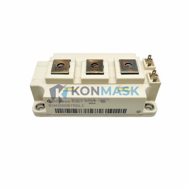
Industrial Drive & Traction Solution – EUPEC BSM200GB170DLC | Infineon IGBT Module
Where This Product Is Used
The EUPEC BSM200GB170DLC is a high-power IGBT module rated at 200 A / 1700 V, engineered for demanding industrial power conversion applications. Engineers and system integrators specify this module across the following sectors:
- Variable Frequency Drives (VFD) & AC Motor Drives – Medium-voltage drive systems for pumps, compressors, fans, and conveyor lines in process industries.
- Industrial UPS & Energy Storage Systems – Three-phase inverter stages requiring high blocking voltage and low switching losses.
- Traction & Rail Applications – Auxiliary converters and traction inverters in light rail, metro, and industrial locomotives.
- Renewable Energy Inverters – Grid-tie inverters for wind turbine converters and large-scale solar PV systems.
- Welding & Induction Heating Equipment – High-frequency power stages demanding robust short-circuit withstand capability.
- STATCOM / SVG & Power Quality Equipment – Reactive power compensation systems in utility and industrial substations.
Technical Specifications
| Part Number | BSM200GB170DLC |
| Manufacturer | EUPEC (Infineon Technologies) |
| Module Type | Dual IGBT + Freewheeling Diode (Half-Bridge) |
| Collector Current (IC) | 200 A (TC = 25°C) |
| Collector-Emitter Voltage (VCES) | 1700 V |
| Gate-Emitter Voltage (VGES) | ±20 V |
| Saturation Voltage (VCE(sat)) | Typ. 2.7 V @ 200 A |
| Switching Frequency | Up to 2 kHz (application-dependent) |
| Operating Junction Temp. (Tj) | -40°C to +150°C |
| Package / Footprint | 62mm Standard Module (DLC Housing) |
| Isolation Voltage | 4000 VRMS |
| Weight | Approx. 280 g |
| RoHS Compliance | Yes |
Why Engineers Specify This Model
- 1700 V blocking voltage provides the necessary safety margin for 690 V AC bus systems, eliminating the need for over-rated alternatives.
- DLC (Dual Low-loss Chip) technology from EUPEC/Infineon delivers reduced switching losses (Eon + Eoff), directly lowering heat sink requirements and improving system efficiency.
- 62mm standard footprint ensures drop-in compatibility with existing drive platforms and simplifies MRO replacement without PCB redesign.
- Integrated freewheeling diodes with optimized reverse recovery characteristics reduce EMI and simplify gate driver design.
- Robust short-circuit withstand time (tsc ≥ 10 µs) provides protection margin for gate driver fault response.
- Isolated baseplate (AlSiC or Cu) enables direct mounting to water-cooled or air-cooled heat sinks without additional isolation pads in most configurations.
Complete System Bill of Materials
When designing or servicing a drive system around the BSM200GB170DLC, the following complementary components are typically required:
- Gate Driver Board – Isolated gate driver IC (e.g., Infineon 1ED020I12-F2, CONCEPT 2SD315AI) with ±15 V / +15 V / -8 V supply rails
- DC Bus Capacitor Bank – Film capacitors rated ≥ 1800 V DC, sized for ripple current at target switching frequency
- Heat Sink & Thermal Interface – Extruded aluminum or liquid-cooled cold plate; thermal paste (e.g., Dow TC-5026) or phase-change pad
- DC Bus Fuse – Semiconductor-grade fast-acting fuse (e.g., Bussmann 170M series) rated for 1700 V DC
- Current Sensor – Hall-effect or Rogowski coil sensor for phase current feedback
- Snubber / dV/dt Filter – RC snubber network across module terminals to suppress voltage spikes
- Mounting Hardware – M6 screws, torque-controlled to manufacturer specification (typically 3–4 N·m)
Compliance & Industry Standards
- RoHS 2011/65/EU – Compliant; lead-free solder construction
- IEC 60747-9 – Discrete semiconductor devices: Insulated-gate bipolar transistors (IGBTs)
- EN 50178 – Electronic equipment for use in power installations
- UL Recognized Component – Suitable for integration into UL-listed end equipment
- CE Marking – Meets applicable EU directives for industrial electronic components
Quality Assurance & Sourcing
At Konmask.com, every IGBT module undergoes a structured verification process before dispatch:
- ✔ Authenticity Check – Part markings, date codes, and lot numbers cross-referenced against manufacturer records
- ✔ Visual Inspection – Baseplate flatness, terminal condition, and housing integrity verified per IPC-A-610 criteria
- ✔ Functional Screening – VCE(sat) and leakage current spot-checked on representative samples
- ✔ Traceability – Full supply chain documentation available upon request for MRO and OEM customers
- ✔ Packaging – Anti-static tray or original OEM packaging; double-boxed for international shipment
How to Source This Part
The BSM200GB170DLC is available for immediate inquiry through Konmask.com. We serve OEM manufacturers, system integrators, MRO procurement teams, and field service engineers across China and international markets.
- Request a Quote: Submit your BOM or part number via support@konmask.com
- Lead Time: Ex-stock and short lead-time options available — contact us for current inventory status
- MOQ: Single-unit orders accepted; volume pricing available for 5+ units
- Payment: T/T, L/C, and trade assurance options supported
- Export: Experienced in CN customs documentation, HS code classification, and international logistics
Application-Specific FAQ
Q: Can the BSM200GB170DLC replace a BSM200GB120DN2 in an existing drive?
A: The 170DLC offers a higher voltage class (1700 V vs. 1200 V) and uses the same 62mm footprint. Electrical compatibility must be verified against gate driver supply voltage and VGE thresholds. Consult your drive OEM or contact Konmask for application support.
Q: What gate resistance (Rg) is recommended?
A: EUPEC recommends Rg,on = 2.2 Ω and Rg,off = 2.2 Ω as a starting point. Adjust based on measured dV/dt and EMI performance in your specific layout.
Q: Is this module suitable for parallel operation?
A: Yes, with careful attention to current sharing — matched VCE(sat) bins, symmetric bus bar layout, and individual gate resistors per module are required. Contact us for matched-pair sourcing.
Q: What thermal interface material do you recommend?
A: Dow Corning TC-5026 or equivalent with thermal conductivity ≥ 3 W/m·K. Apply uniformly at 0.1–0.15 mm bond line thickness. Torque mounting screws to 3 N·m in a cross pattern.
Q: Do you provide datasheets and application notes?
A: Yes. Official Infineon/EUPEC datasheets and relevant application notes are available upon request with every order.
© 2026 Konmask.com. All rights reserved.
Original Source: https://Konmask.com
Contact: support@konmask.com | +0086 19859288691