
Magnetoresistive SZCB-01 – Non-Contact Rotational Speed Measurement | SZCB Series
Engineering Background
In high-demand industrial environments — from steel rolling mills to wind turbine gearboxes — accurate shaft speed measurement is non-negotiable. Traditional inductive sensors degrade in contaminated or high-vibration environments. The SZCB-01 leverages magnetoresistive (MR) technology to deliver stable, interference-resistant speed signals even under extreme operating conditions, making it the preferred choice for process engineers who cannot afford measurement drift.
Product Positioning
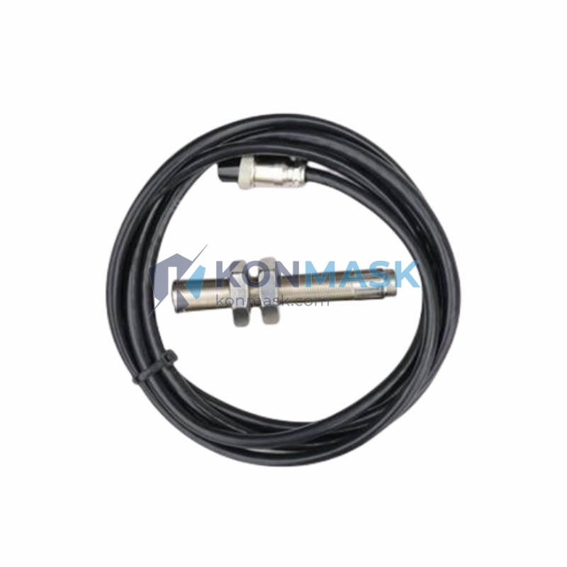
The SZCB-01 is a non-contact magnetoresistive speed sensor designed for continuous rotational speed (RPM) monitoring of ferromagnetic gear wheels, toothed rings, and encoder discs. It outputs a clean digital pulse signal compatible with PLCs, DCS controllers, and dedicated speed monitoring relays. Sourced and verified by Konmask.com for B2B industrial procurement.
Complete Technical Specifications
- Model: SZCB-01
- Sensing Technology: Magnetoresistive (MR)
- Measurement Target: Ferromagnetic gear / toothed wheel
- Output Signal: Digital pulse (square wave)
- Supply Voltage: 5–24 VDC (typical; confirm with datasheet)
- Operating Temperature: -40°C to +120°C
- Protection Rating: IP67 (dust-tight, water-resistant)
- Housing Material: Stainless steel / engineering plastic
- Mounting Thread: M12 or M18 (application-dependent)
- Cable Length: Standard 1 m / 2 m shielded cable
- Weight: Approx. 100 g
- Frequency Response: Up to several kHz (gear-tooth dependent)
- Air Gap (Sensing Distance): 0.1–3 mm (recommended)
Proven Application Environments
- Steel & Metals Processing: Rolling mill main drive shaft speed feedback to PLC speed loops
- Wind Energy: Gearbox low-speed shaft and high-speed shaft RPM monitoring for SCADA systems
- Paper & Pulp: Dryer section roll speed synchronization
- Mining & Conveying: Belt conveyor drive pulley speed monitoring and slip detection
- Marine Propulsion: Propeller shaft RPM feedback to engine management systems
- Cement & Aggregate: Kiln drive and bucket elevator speed supervision
- Power Generation: Turbine auxiliary shaft speed monitoring
- General Machinery: Any rotating shaft with a ferromagnetic toothed target wheel
Engineering Advantages
- Non-Contact Operation: Zero mechanical wear; indefinite service life under normal conditions
- Magnetoresistive Principle: Superior signal quality vs. variable-reluctance sensors at low RPM — no signal dropout near zero speed
- High Vibration Immunity: Solid-state sensing element withstands shock and vibration per IEC 60068-2
- Wide Temperature Range: Reliable from sub-zero cold-start to high-temperature process environments
- EMI Resistance: Shielded cable and differential output option minimize noise pickup in VFD-heavy environments
- Direct PLC/DCS Compatibility: TTL/HTL output levels selectable to match Siemens, ABB, Rockwell, and Mitsubishi input modules
- Compact Form Factor: M12/M18 threaded body fits standard proximity sensor mounting brackets — no custom machining required
System Architecture & Signal Flow
The SZCB-01 integrates into a typical speed monitoring loop as follows:
- Target Wheel → Rotating ferromagnetic gear tooth passes sensor face
- SZCB-01 MR Element → Detects magnetic field variation; outputs digital pulse per tooth
- Signal Cable → Shielded, routed away from power cables (min. 200 mm separation)
- PLC/DCS High-Speed Counter Input → Counts pulses; calculates RPM = (Pulses/sec × 60) ÷ Teeth count
- Speed Monitoring Relay (optional) → Overspeed / underspeed alarm output to safety circuit
- HMI / SCADA → Real-time RPM display and trend logging
Recommended wiring: Use twisted-pair shielded cable (Belden 9841 or equivalent). Ground shield at control panel end only to avoid ground loops.
Sourcing & Quality Verification
- Authorized Distribution: Konmask.com sources SZCB-01 units through verified industrial supply channels with full traceability
- Incoming Inspection: Each unit undergoes dimensional check, output signal verification, and insulation resistance test before dispatch
- Counterfeit Prevention: Batch documentation and manufacturer markings verified against reference samples
- Packaging: Anti-static bag + foam-lined carton; sensor face protected with plastic cap during transit
- Warranty: 12-month warranty against manufacturing defects from date of shipment
- Certifications: CE marking; RoHS compliant; application-specific ATEX variants available on request
Procurement Process
- Step 1 – Inquiry: Submit your required quantity, target gear tooth count, supply voltage, and output type via email or the contact form
- Step 2 – Quotation: Receive formal quotation with lead time within 1 business day
- Step 3 – Order Confirmation: Issue PO or confirm via email; proforma invoice issued for payment
- Step 4 – Dispatch: Standard lead time 3–7 business days; express DHL/FedEx available
- Step 5 – Documentation: Packing list, commercial invoice, and test report included with shipment
- Step 6 – After-Sales: Technical support available via email and WhatsApp for installation and commissioning queries
Technical FAQ
Q: Can the SZCB-01 detect speed on a smooth shaft without a gear wheel?
A: No. The magnetoresistive principle requires a ferromagnetic toothed target. A minimum of 20–60 teeth is recommended for accurate low-speed measurement. Retrofit target wheels are available.
Q: What is the minimum detectable speed?
A: Unlike variable-reluctance sensors, MR sensors can detect near-zero RPM (quasi-static). Practical minimum is typically 0.1 RPM with a 60-tooth wheel.
Q: Is the output compatible with Siemens S7-1200/1500 HSC inputs?
A: Yes. Select the 24 VDC HTL output variant. Configure the HSC in frequency measurement mode. Pulse frequency = RPM × teeth ÷ 60.
Q: Can it be used in ATEX Zone 1 or Zone 2 hazardous areas?
A: Standard SZCB-01 is not ATEX-rated. Contact Konmask.com for ATEX-certified variants suitable for Zone 1/2 gas or Zone 21/22 dust environments.
Q: What is the recommended air gap between sensor and gear tooth?
A: 0.5–1.5 mm is optimal. Maximum reliable gap is approximately 3 mm depending on tooth geometry and module size.
Q: How do I verify the sensor is working before installation?
A: Power the sensor and pass a ferromagnetic object (e.g., screwdriver blade) across the face at 1–2 Hz. Observe the output with a multimeter or oscilloscope — you should see clean switching between high and low states.
© 2026 Konmask.com. All rights reserved.
Original Source: https://Konmask.com
Contact: support@konmask.com | +0086 19859288691