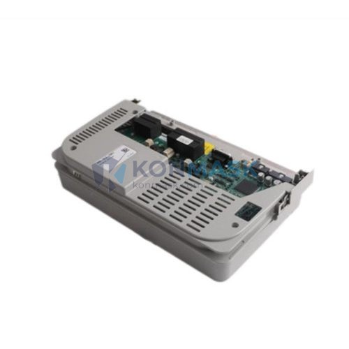

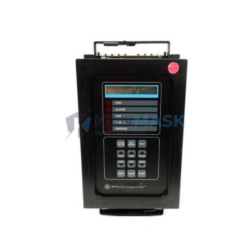
GE | 269PLUS-100P-120 — Motor Management Relay | MULTILIN 269 Plus Series
Engineering Background: The GE MULTILIN 269 Plus series occupies a critical position in industrial motor protection architecture. Deployed across medium-voltage motor control centers (MCCs) and low-voltage switchgear, it serves as the primary intelligence layer between the power system and rotating machinery. In a typical DCS/SCADA-integrated plant, the 269 Plus acts as both a protection device and a data acquisition node — reporting thermal state, current imbalance, and fault history upstream to the control system via serial or hardwired I/O. The 269PLUS-100P-120 specifically is the 100A CT-input, 120V AC control power variant, designed for direct integration into standard North American and IEC-compliant motor starter panels.
Product Positioning: Within the 269 Plus family, the -100P suffix denotes a 100A phase CT input rating with a built-in power meter function, distinguishing it from the base -100 model which lacks power metering. The -120 suffix specifies 100–240V AC/DC control power input, making it compatible with both 120V AC and 110V DC station battery-backed control circuits — a critical boundary condition for substation and offshore applications where control power source varies. It is not interchangeable with the -24 (24V DC) variant without control power rewiring.
Complete Technical Specifications
Electrical
- Phase CT Input Rating: 100A (secondary 1A or 5A selectable)
- Control Power Supply: 100–240V AC / 100–250V DC (±20%)
- Frequency: 50/60 Hz
- Output Relays: 4 × Form C (SPDT), 8A @ 250V AC
- Analog Output: 4–20 mA (optional, for thermal capacity or current)
- Communications: RS-485 Modbus RTU (19.2 kbps)
- Digital Inputs: 5 × optically isolated, 24–250V AC/DC
- Power Consumption: ≤ 15 VA (AC), ≤ 10 W (DC)
Mechanical
- Mounting: Panel flush-mount, 1/4-turn fasteners
- Cutout Dimensions: 138 × 138 mm (standard square)
- Depth Behind Panel: 165 mm
- Weight: Approx. 0.9 kg
- Terminal Type: Removable screw-clamp, rear-access
- Display: 2 × 16 character backlit LCD + 12 LED indicators
Environmental
- Operating Temperature: −20°C to +60°C
- Storage Temperature: −40°C to +85°C
- Humidity: 5–95% RH, non-condensing
- Pollution Degree: 2 (IEC 60664-1)
- Altitude: Up to 2000 m without derating
- Vibration: IEC 60255-21-1, Class 1
- Shock: IEC 60255-21-2, Class 1
Certifications
- UL Listed: UL 508 (Industrial Control Equipment)
- CSA Certified: C22.2 No. 14
- CE Marked: EMC Directive 2014/30/EU, LVD 2014/35/EU
- IEC 60255 Series: Protection relay standard compliance
Data source: GE Grid Solutions / GE MULTILIN 269 Plus Motor Management Relay Instruction Manual (GEK-106288), publicly available technical datasheet.
Proven Application Environments
- Petrochemical Refinery: Crude distillation column feed pump (250 kW, 6.6 kV) — continuous duty with frequent thermal cycling; relay monitors thermal capacity utilization and inhibits restart until safe cool-down is confirmed.
- Thermal Power Plant: Boiler feed water pump motor (MV, 11 kV) — high-inertia start with locked-rotor protection; 269PLUS enforces jam protection and start inhibit after consecutive failed starts.
- Municipal Water Treatment: Raw water intake pump station — unattended remote site; Modbus RTU integration to SCADA enables remote fault acknowledgment and motor status monitoring without site visit.
- Offshore Oil Platform: Seawater lift pump (hazardous area MCC) — DC station battery control power (110V DC); -120 variant operates reliably on battery-backed DC bus during AC power loss.
- Pulp & Paper Mill: Refiner plate motor (high cyclic load) — current unbalance and negative sequence protection prevents winding damage from chronic supply asymmetry in heavy industrial environments.
- Mining Concentrator: Ball mill drive motor (soft-start application) — acceleration time monitoring and stall protection configured to accommodate extended ramp-up profiles without nuisance tripping.
Engineering Advantages
- For high-inertia loads with extended start times, this motor management relay provides configurable acceleration time supervision (1–250 s), because a fixed overcurrent element would cause nuisance trips during legitimate slow starts.
- For plants with unreliable supply voltage, this relay provides negative sequence current detection with independent trip threshold, because phase reversal and voltage unbalance are leading causes of premature winding failure in three-phase motors.
- For remote unmanned substations, this relay provides Modbus RTU communications with 32 pre-mapped data registers, because operators require real-time thermal state and fault code retrieval without dispatching field personnel.
- For applications requiring post-fault analysis, this relay provides a non-volatile fault history log (last 5 events with timestamp and pre-fault currents), because root-cause investigation demands data captured at the moment of trip, not reconstructed afterward.
- For motor fleets with mixed CT ratios, this relay provides software-configurable CT ratio (1–6000:5 or 1:1), because a single relay model can be standardized across multiple motor sizes without hardware changes.
- For sites with strict panel space constraints, this relay provides a 138 × 138 mm standard cutout footprint compatible with existing IEC/NEMA panel knockouts, because retrofit projects cannot accommodate non-standard cutout modifications.
System Architecture & Signal Flow
Signal Flow: Phase currents → external CTs (100:5 or 100:1) → relay current inputs (terminals 1–6) → DSP-based thermal model + protection algorithms → output relay contacts (trip/alarm/auxiliary) → motor contactor coil / DCS digital input. Ground fault current → core balance CT or residual connection → relay GF input (terminals 7–8). Modbus RTU data → RS-485 port (terminals 21–22) → DCS/SCADA serial gateway.
Compatible Models & Reason:
- 269PLUS-100P-24: Identical protection functions; differs only in control power (24V DC). Compatible for same motor sizes; requires DC control power source.
- 269PLUS-100-120: Same control power; lacks integrated power metering (-P suffix). Suitable where kW/kVAR measurement is not required by the SCADA system.
- GE 369 Motor Management Relay: Upward-compatible successor with IEC 61850 GOOSE and additional protection elements. Recommended for new greenfield projects requiring substation automation protocol support.
Substitution Conditions: The 269PLUS-100P-120 may be substituted with the 369 series only if panel cutout is modified (369 uses a different form factor) and firmware configuration is rebuilt from scratch. Direct drop-in replacement within the 269 Plus family requires matching the CT input rating and control power suffix.
Sourcing & Quality Verification
Units offered through Konmask.com are sourced from authorized industrial surplus channels, OEM decommissioning programs, and verified secondary market distributors. Each unit undergoes a structured incoming inspection before listing.
4-Step Verification Process:
- Physical Inspection: Housing integrity check, terminal block condition, LCD/LED function test, and label legibility verification against GE nameplate standards.
- Firmware Version Confirmation: Firmware revision read from relay menu and cross-referenced against GE MULTILIN release history to confirm no end-of-life or recalled firmware versions.
- Functional Power-On Test: Control power applied at rated voltage; self-test sequence completion confirmed; no active fault codes present.
- Communication Port Test: RS-485 Modbus RTU query executed; device responds with correct model identification register (Register 1000h).
Documentation Available Upon Request:
- GE MULTILIN 269 Plus Instruction Manual (GEK-106288)
- Unit-specific inspection checklist with technician sign-off
- Firmware version report
- Communication test log (Modbus register dump)
- Certificate of conformance (where available from original supply chain)
Procurement Process
- Inquiry Submission: Submit your model number, required quantity, and delivery timeline via the contact form or directly to support@konmask.com. Include your application voltage and CT ratio if known — this allows confirmation that the -120 control power variant matches your panel design.
- Technical Confirmation & Quotation: A response with stock confirmation, unit condition report, and firm pricing will be provided within 24 hours on business days. For urgent plant shutdowns or emergency replacements, same-day response is prioritized — please indicate urgency in the subject line.
- Order Fulfillment & Shipping: Units are packed in anti-static foam with original-style protective packaging. Export documentation (commercial invoice, packing list, HS code 8536.49) is prepared for international shipments. Tracking information is provided upon dispatch.
Technical Support: Pre-sale support covers parameter setting guidance, CT ratio selection, and compatibility confirmation with existing GE MULTILIN systems. Post-sale support includes commissioning parameter templates and Modbus register map reference for DCS integration teams.
Technical FAQ
- Q: Is the 269PLUS-100P-120 compatible with a 5A secondary CT, or does it require a 1A secondary?
- A: The 269 Plus accepts both 1A and 5A CT secondaries — the CT ratio is configured in software (Menu → Motor Setup → CT Ratio). No hardware modification is required. Confirm the secondary rating of your existing CTs before commissioning to set the correct ratio and avoid measurement error.
- Q: Can the 269PLUS-100P-120 directly replace a 269PLUS-100-120 (without the -P suffix) in an existing panel?
- A: Yes — the -P variant is a drop-in replacement for the non-P model. The terminal layout, cutout dimensions, and control power requirements are identical. The -P adds power metering registers (kW, kVAR, PF) accessible via Modbus; these registers simply return zero on the non-P model. No wiring changes are required.
- Q: Is this relay certified for use in SIL-rated safety instrumented systems (SIS)?
- A: The 269 Plus series is not independently SIL-certified under IEC 61508. It is suitable for motor protection in general industrial applications and process control systems. For SIL 1/2 motor protection requirements, GE recommends the dedicated safety relay variants or a separate SIL-certified safety relay in series with the 269 Plus trip output. Confirm SIS requirements with the plant safety engineer before specifying this relay in a safety loop.
© 2026 Konmask.com. All rights reserved.
Original Source: https://Konmask.com
Contact: support@konmask.com | +0086 19859288691