
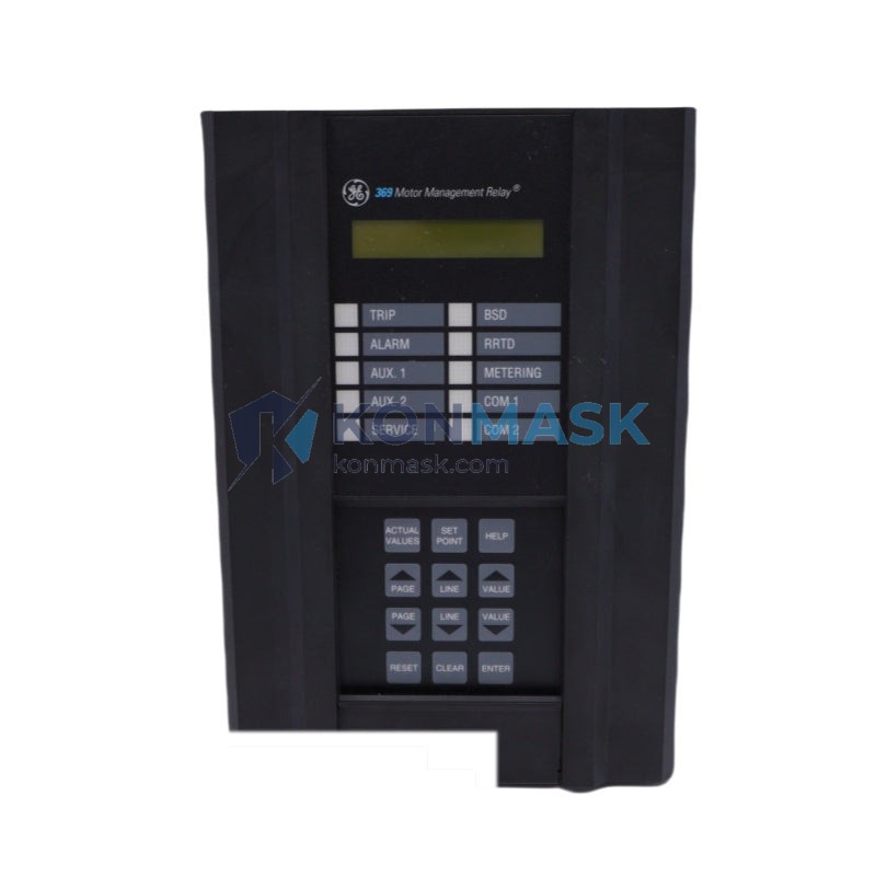

GE Multilin 369-HI-R-M-0-0-0 – Advanced Motor Management Relay | Multilin 369 Platform
Engineering Background
The GE Multilin 369 Motor Management Relay is a purpose-built protection and control device developed by GE Grid Solutions (formerly GE Multilin) for medium-voltage and low-voltage AC induction motors in demanding industrial environments. The 369 platform has been a benchmark in motor protection engineering for over two decades, trusted by utilities, petrochemical plants, mining operations, and heavy manufacturing facilities worldwide.
Product Positioning
The 369-HI-R-M-0-0-0 variant is configured for high-current input (HI), RS-485 communications (R), and Modbus RTU protocol (M), making it the preferred choice for SCADA-integrated motor control centers (MCCs) and distributed control system (DCS) architectures. It delivers comprehensive thermal, overcurrent, undercurrent, ground fault, and phase unbalance protection in a single 1/4 DIN panel-mount chassis.
Complete Technical Specifications
| Manufacturer | GE Grid Solutions (GE Multilin) |
| Model / SKU | 369-HI-R-M-0-0-0 |
| Series / Platform | Multilin 369 Motor Management Relay |
| Input Current Range | High Current (HI): 1–12 A (CT secondary) |
| Nominal Frequency | 50 / 60 Hz |
| Control Power Supply | 20–60 V DC / 20–48 V AC (standard aux) |
| Communications Port | RS-485 (2-wire, half-duplex) |
| Protocol | Modbus RTU |
| Relay Outputs | 4 × Form-C output relays (Trip + Alarm) |
| Digital Inputs | 6 × programmable digital inputs |
| Analog Output | 1 × 4–20 mA (motor load / thermal capacity) |
| Display | 2 × 16-character backlit LCD |
| Mounting | 1/4 DIN panel-mount (flush) |
| Enclosure Rating | IP54 (front panel) |
| Operating Temperature | –20°C to +60°C |
| Storage Temperature | –40°C to +85°C |
| Weight | Approx. 3.6 kg |
| Standards Compliance | IEC 60255, UL 508, CSA C22.2 |
| Country of Origin | United States |
Proven Application Environments
- Oil & Gas: Pump motors, compressor drives, and wellhead motor control centers requiring SIL-rated protection logic.
- Mining & Minerals: Conveyor belt drives, crusher motors, and ventilation fan protection in high-dust environments.
- Water & Wastewater: Submersible pump protection with dry-run detection via undercurrent element.
- Petrochemical Plants: Hazardous-area MCC integration with SCADA via Modbus RTU over RS-485 backbone.
- Power Generation: Auxiliary motor protection for boiler feed pumps, cooling water pumps, and ID/FD fans.
- Pulp & Paper / Steel Mills: High-inertia load starting with extended acceleration time supervision.
Engineering Advantages
- Thermal Model Accuracy: Adaptive thermal memory with RTD bias correction (up to 6 × RTD inputs on expanded models) prevents nuisance trips while protecting against true thermal overload.
- Comprehensive Protection Suite: Thermal overload, phase overcurrent (50/51), ground fault (50G/51G), phase unbalance, undercurrent, jam/stall, starts-per-hour, and restart inhibit — all in one device.
- Modbus RTU Integration: Full register map for real-time metering, event log retrieval, and remote setpoint modification via SCADA or DCS.
- Event & Data Logging: 256-event sequential event recorder (SER) with 1 ms time-stamp resolution for post-fault analysis.
- Motor Statistics: Cumulative run hours, number of starts, last start current, and thermal capacity used — critical for predictive maintenance programs.
- Reduced Panel Space: 1/4 DIN form factor consolidates protection, metering, and communications into a single device, eliminating discrete overload relays and separate meters.
System Architecture & Signal Flow
The 369-HI-R-M-0-0-0 sits at the motor feeder level within a Motor Control Center (MCC) or switchgear lineup. Current transformers (CTs) on all three phases and a dedicated ground CT feed the relay’s high-current input module. The relay continuously computes thermal capacity used, compares measured currents against all protection elements, and drives output relays to trip the upstream contactor or circuit breaker on fault detection.
The RS-485 port connects to a Modbus RTU master (PLC, DCS, or SCADA gateway) using a 2-wire shielded twisted-pair cable (up to 1,200 m at 19,200 baud). The 4–20 mA analog output can drive a remote ammeter or feed a DCS analog input card for continuous load monitoring without polling overhead.
Sourcing & Quality Verification
- All units sourced through verified industrial automation distributors and OEM-authorized channels.
- Each relay undergoes incoming inspection: visual check, label verification (model code, serial number, firmware revision), and functional power-on test.
- Original GE Multilin documentation, calibration records, and factory test reports available upon request.
- Genuine GE part — not a third-party clone or remanufactured unit.
Procurement Process
- Confirm compatibility: Verify your CT secondary rating matches the HI input range (1–12 A) and your control power supply voltage.
- Request a quote: Contact support@konmask.com or call +0086 19859288691 for volume pricing and lead time.
- Place order: Purchase directly via this listing. Secure checkout with HKD pricing; international wire transfer and PayPal accepted.
- Shipping: Ships from warehouse within 1–3 business days. DHL / FedEx express available for urgent requirements. Export documentation (commercial invoice, packing list, COO) provided.
- After-sales support: 12-month warranty. Technical support from our engineering team for installation and commissioning queries.
Technical FAQ
Q: What does the model code 369-HI-R-M-0-0-0 mean?
A: 369 = product family; HI = High Current input (1–12 A CT secondary); R = RS-485 communications port; M = Modbus RTU protocol; the three trailing zeros indicate no optional RTD module, no second communications port, and standard firmware.
Q: Can the 369 communicate with a Siemens S7 PLC?
A: Yes. Any Modbus RTU master — including Siemens S7 with a CP341/CP343 module or a third-party Modbus gateway — can poll the 369’s register map for metering data and relay status.
Q: Is the 369-HI-R-M-0-0-0 suitable for motors above 1,000 V?
A: The relay itself operates on CT secondary signals (not line voltage), so it is compatible with medium-voltage motors (up to 15 kV class) when appropriate CTs and VTs are used. The relay’s control power input is rated for low-voltage auxiliary supplies.
Q: What is the difference between the HI and LO current input versions?
A: The HI version accepts 1–12 A CT secondary current, suitable for motors with CTs rated 5 A secondary at full load. The LO version accepts 0.1–1.2 A, intended for smaller motors or higher-ratio CTs. Confirm your CT nameplate before ordering.
Q: Can I upgrade firmware in the field?
A: Firmware upgrades are performed via the RS-485 port using GE’s EnerVista 369 Setup software. Contact our technical team for the latest firmware version compatible with your hardware revision.
© 2026 Konmask.com. All rights reserved.
Original Source: https://Konmask.com
Contact: support@konmask.com | +0086 19859288691