

A temperature trend that slowly moves away from the process reference can lead to an expensive but ineffective PLC repair. The replacement adapter arrives, the channel returns to service, and the same offset remains. The fault may have been in the probe, the cable or the interpretation of the measurement rather than the electronics that were ordered.
For a Mitsubishi FX3U installation using Pt100 inputs, the purchasing decision should follow a measurement-boundary check. The aim is not to delay a necessary replacement. It is to identify what a new adapter can reasonably be expected to fix, and what evidence should accompany the request.
First decide what “wrong temperature” means
A disagreement between two temperature readings is not automatically an instrument fault. The sensors may be at different insertion depths, attached to different surfaces or responding at different rates. A reference taken after the process changes may not represent the condition recorded by the PLC earlier. Before changing hardware, confirm that the readings describe the same physical point and time.
Separate three observations in the fault report: a stable offset, an intermittent disturbance and a slow response. They suggest different investigation paths. Record when the symptom appears, whether nearby drives or heaters are operating, and whether other channels change at the same time. These observations are useful evidence, not proof of a particular failed component.
Confirm the interface before choosing the spare
Mitsubishi’s FX3U-4AD-PT-ADP manual describes a four-channel adapter for three-wire Pt100 resistance thermometers. It also discusses analog cable separation, shielding and interference precautions. That is a specific measurement interface, not a universal temperature input for every sensor described as an RTD.
The FX3U-4AD-PT-ADP temperature adapter is therefore a relevant replacement candidate only after the installed sensor and interface are confirmed. A Pt1000 probe or a thermocouple should not be treated as the same input because it measures temperature. Check the complete sensor specification, wiring arrangement and the approved configuration rather than relying on a handwritten cabinet label.
The host also belongs in the record. An installation built around an FX3U-80MR/ES controller needs its actual hardware version and adapter connection arrangement checked against the manufacturer’s compatibility information. The controller link identifies a possible installed host; it does not mean an adapter can be attached without the required interface components or review.
Use two test boundaries, not one guess
The first useful boundary is the adapter input itself. Under an approved, isolated test procedure, qualified personnel can compare its response to a suitable traceable resistance simulation. This asks whether the electronics and configured interpretation produce an acceptable result for a known input. The test should state the selected points, tolerance and reference-instrument uncertainty before anyone declares a pass.
The second boundary includes the field cable. Comparing a controlled signal at the field end with one at the cabinet end can help localize an added error. The result must be interpreted in the context of the actual three-wire arrangement and manufacturer instructions. Do not improvise live jumpers or probe connections on an operating process. Protect the process, isolate the equipment as required and use authorized procedures.
A useful conclusion is specific: “the adapter passed the agreed input simulation, while the field-path test remained outside tolerance.” That supports investigation of the remaining path. “The PLC is bad” does not. Conversely, a repeatable failure at the adapter boundary with a verified setup supports a more focused spare request, without claiming that every upstream component has been cleared.
Read the pattern across channels
If all channels move together, look for a shared condition before buying four probes. If one channel changes only when a particular machine operates, preserve that timing information. If the apparent offset disappears when a connection is disturbed, do not erase the original observation by immediately recalibrating everything. Intermittent faults need a record of the condition in which they occur.
These patterns guide investigation; they do not establish a diagnosis by themselves. A shared symptom can arise from several causes, including the process reference used for comparison. Keep the original trend and annotate the time of each test. This is more valuable than a final screenshot that shows only the temporarily improved reading.
Be cautious with averaging and software offsets. Smoothing can make a noisy trend easier to read while hiding a developing connection problem. An offset can make one operating point agree while leaving the rest of the range wrong. Any compensation should have a documented engineering basis, not serve as an emergency substitute for understanding the measurement error.
Make the purchase conditional on an acceptance plan
Before ordering, define the result that would count as a successful repair. For example, the plant may require agreement at several relevant test points, stable readings over a defined observation period and correct process alarms after reinstatement. Those limits come from the application and quality requirements. There is no universal tolerance suitable for every heater, batch vessel and environmental monitor.
Ask the supplier to identify the exact offered adapter, its condition and any documented test scope. A general functional test may support purchasing confidence, but it is not a calibration certificate for your complete installed measurement chain. Confirm which connectors or accessories are included so the repair does not stall over an unlisted item.
Keep the removed part segregated until the diagnosis is settled. Mark whether it is proven faulty, suspected or awaiting investigation. Returning an untested suspect adapter to general stock creates a future outage risk; discarding it immediately may also remove evidence of a cable problem that has not been fixed.
Questions buyers and technicians ask
Will a new adapter remove every temperature offset?
No. It cannot correct a misplaced probe, an incorrect sensor type or an error outside its own measurement boundary. Establish which portion of the chain failed before treating replacement as the complete remedy.
Can a two-wire or four-wire probe be connected by assumption?
No. The documented adapter interface is three-wire Pt100. Any proposed arrangement must be checked against the manufacturer’s instructions and the required measurement accuracy; wire count alone is not an approved conversion method.
Is a stable reading enough to accept the repair?
Stability and accuracy are different properties. A consistently wrong reading can look reassuring. Compare against an appropriate reference and the pre-agreed acceptance limits, then confirm the installed process response.
What should the inquiry include?
Provide adapter and host references, sensor type, a brief symptom description, quantity and delivery destination. Include available test evidence and identify its boundary. Avoid sending an unexplained trend image as the only fault description.
For a precise FX3U temperature-input spare quotation, contact Konmask at support@konmask.com. We can clarify the offered reference and package scope while your engineering team retains responsibility for diagnosis, installation and measurement acceptance.
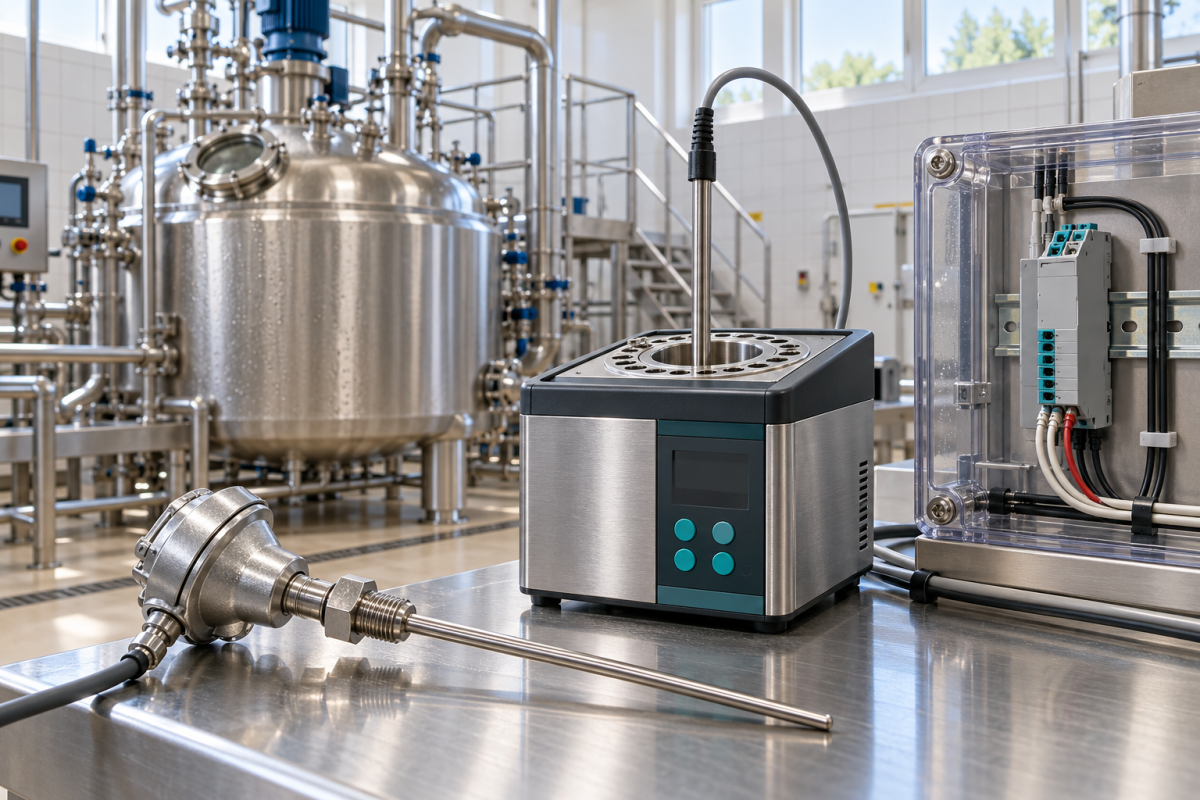
Image: AI-generated editorial illustration, not an exact product photograph or installation reference.
© 2026 Konmask. All rights reserved. Official Website: https://www.konmask.com Inquiry: support@konmask.com | WhatsApp/Tel: +86 19859288691
