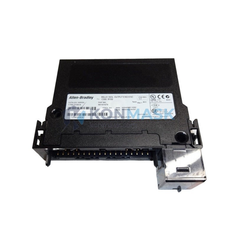
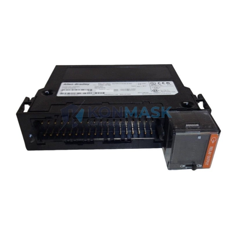
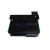
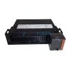
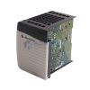
Allen-Bradley 1756-OX8I – AC/DC Isolated Relay Output Module | ControlLogix 1756 Platform
Engineering Background: The Allen-Bradley ControlLogix 1756 platform is Rockwell Automation’s flagship process and discrete control architecture, deployed across critical infrastructure in petrochemical refining, power generation, and municipal water treatment. Within this architecture, output modules serve as the final control element interface—translating controller logic into physical switching actions on field devices. The 1756-OX8I occupies a specific and non-substitutable role: it provides fully isolated relay contacts for applications where electrical separation between the controller backplane and field circuits is a hard safety or regulatory requirement.
Product Positioning: The 1756-OX8I is distinguished from non-isolated relay output modules (such as the 1756-OW16I or 1756-OB series) by its point-to-point galvanic isolation architecture—each of the 8 output points maintains independent isolation from all others and from the backplane. This design is mandatory in mixed-voltage field environments, motor starter circuits, and any installation where ground loops or fault propagation between output channels must be eliminated. It is not a general-purpose high-density output module; it is selected specifically when isolation integrity is the primary engineering constraint.
Complete Technical Specifications
Electrical
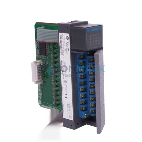
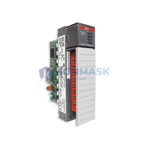
- Output Points: 8 (fully isolated, point-to-point)
- Output Type: Relay (Form C – SPDT)
- Load Voltage Range: 10–265V AC / 5–125V DC per point
- Maximum Load Current: 2A per point (AC or DC)
- Minimum Load Current: 10 mA
- Isolation Voltage: 2,546V AC (channel-to-channel and channel-to-backplane)
- Backplane Current Draw: 75 mA @ 5V DC; 2 mA @ 24V DC
- Power Dissipation: 5.75W maximum
- Output Indicator: Per-point LED status
Mechanical
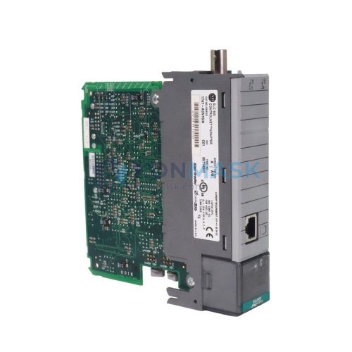
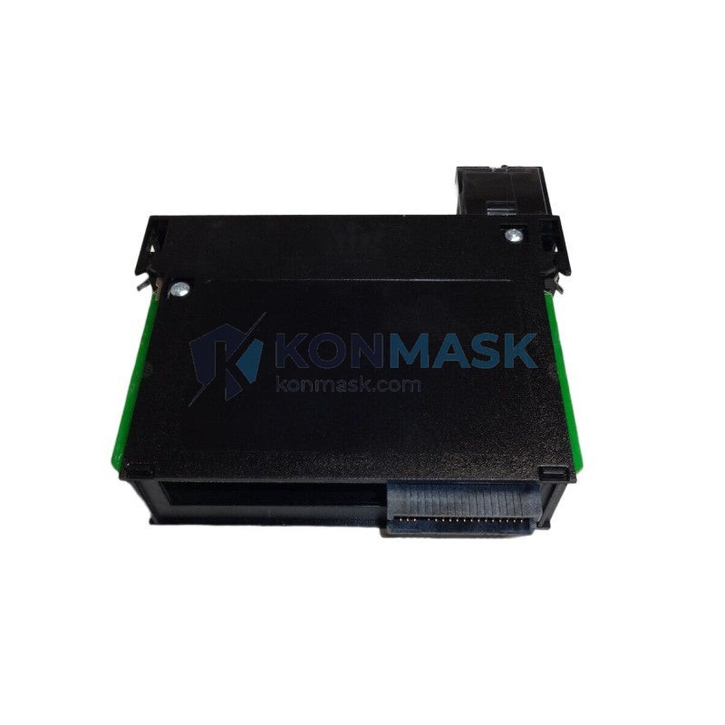
- Form Factor: 1756 ControlLogix single-slot module
- Wiring: Removable terminal block (RTB), 20-pin
- Weight: Approximately 300 g (module only)
- Dimensions: Standard 1756 chassis slot profile
Environmental
- Operating Temperature: 0°C to +60°C
- Storage Temperature: -40°C to +85°C
- Relative Humidity: 5–95% non-condensing
- Vibration: IEC 68-2-6 compliant
- Shock: IEC 68-2-27 compliant
- Enclosure Rating: IP20 (panel-mount installation required)
Certifications
- UL Listed (UL 508)
- CE Marked (EMC Directive, Low Voltage Directive)
- CSA Certified
- FM Approved (Class I, Division 2, Groups A–D)
- ATEX Category 3 (Zone 2)
Specification data sourced from Rockwell Automation Publication 1756-TD001 and 1756-UM058. Verify against current revision for safety-critical applications.
Proven Application Environments
- Petrochemical Refining: Crude distillation unit | Motor starter control for pump drives | Continuous 24/7 operation with mixed 120V AC / 24V DC field circuits requiring channel isolation to prevent cross-fault propagation
- Power Generation: Gas turbine auxiliary systems | Solenoid valve and breaker trip coil switching | High-voltage field environment where backplane isolation is a protection relay coordination requirement
- Municipal Water Treatment: Lift station control panels | Submersible pump start/stop sequencing | Wet environment installations with strict ground isolation requirements per IEC 60364
- Pharmaceutical Manufacturing: Clean-in-place (CIP) skids | Valve actuator control in classified areas | FM/ATEX Zone 2 compliance mandated by facility safety case
- Pulp & Paper: Recovery boiler control systems | High-temperature area valve switching | Mixed AC/DC field wiring from legacy instrumentation requiring relay isolation
- Mining & Minerals Processing: Conveyor drive control | Overload relay feedback and motor contactor switching | Dusty, high-vibration environments with IEC 68-2-6 shock/vibration compliance required
Engineering Advantages
- For mixed-voltage field environments, this relay output module eliminates cross-channel fault risk, because each of the 8 points maintains independent galvanic isolation rated to 2,546V AC—no shared return path exists between channels.
- For motor starter and contactor switching applications, this module provides reliable make/break performance at 2A per point, because the Form C (SPDT) relay contact architecture supports both energize-to-trip and de-energize-to-trip wiring configurations without external interposing relays.
- For installations in FM Class I Division 2 or ATEX Zone 2 classified areas, this module satisfies hazardous location requirements natively, because it carries FM and ATEX Category 3 approvals without requiring additional barriers or zener diode assemblies.
- For legacy system integration, this module accepts field wiring from 5V DC to 265V AC on the same backplane, because the wide load voltage range accommodates both modern 24V DC instrumentation and older 120/240V AC control circuits within a single chassis.
- For maintenance-intensive facilities, this module reduces downtime during field wiring changes, because the removable terminal block (RTB) design allows the wiring harness to remain connected while the module is extracted and replaced.
- For high-availability process control, this module supports Rockwell’s ControlLogix redundancy architecture, because it is compatible with 1756-SRM redundancy modules and maintains output state through controller switchover events when configured correctly.
System Architecture & Signal Flow
Signal Flow: ControlLogix CPU (1756-L series) → 1756 backplane (ControlBus) → 1756-OX8I output module → isolated relay contact closure → field device (motor starter coil, solenoid valve, pilot light, or trip relay). Each channel’s relay coil is driven by the module’s internal logic, which receives output tag data from the controller scan cycle. The isolated contact presents a clean, floating switching element to the field circuit—no common reference to backplane ground.
Compatible Controllers & Chassis:
- 1756-L6x, 1756-L7x, 1756-L8x series ControlLogix CPUs (all revisions)
- 1756-A4, 1756-A7, 1756-A10, 1756-A13, 1756-A17 chassis
- 1756-SRM redundancy module (for high-availability configurations)
- Compatible with Studio 5000 Logix Designer (all current versions) via standard Add-On Profile (AOP)
Substitution Conditions: The 1756-OX8I may be considered for replacement by the 1756-OW16I only when point count takes priority over isolation and field voltage does not exceed 240V AC. Direct substitution with solid-state output modules (1756-OB series) is not appropriate for inductive load switching without external suppression. Any substitution must be validated against the application’s isolation voltage requirements and certified area classification.
Sourcing & Quality Verification
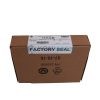
Konmask.com sources the 1756-OX8I through established industrial automation distribution channels, with traceability to original manufacturer packaging. Each unit offered is subject to the following verification process before dispatch:
- Visual & Cosmetic Inspection: Housing integrity, label legibility, connector pin condition, and RTB locking mechanism function checked against OEM reference standards.
- Firmware & Revision Verification: Module series letter and firmware revision confirmed and documented. Customers requiring a specific revision (e.g., Series B vs. Series C) should specify at time of inquiry.
- Functional Bench Test: Output relay actuation verified on each channel using a ControlLogix test chassis prior to shipment on request.
- Packaging & ESD Compliance: Modules are packed in anti-static bags with foam cushioning; shipment includes desiccant for humidity-sensitive transit routes.
Documentation available upon request: Rockwell Automation Certificate of Conformance, test report, commercial invoice with HS code declaration, and packing list with serial number traceability.
Procurement Process
- Submit Inquiry: Contact Konmask.com via email at support@konmask.com or by phone at +0086 19859288691. Provide the part number (1756-OX8I), required quantity, target delivery date, and any revision or certification requirements.
- Receive Quotation: A formal quotation including unit price, lead time, shipping options, and available documentation will be issued within 24 hours of inquiry receipt on business days.
- Order Confirmation & Dispatch: Upon purchase order confirmation, the module is prepared, inspected, and dispatched with full shipping documentation. Technical support for installation, configuration, or compatibility questions is available via email throughout the procurement and commissioning process.
Technical Support Scope: Pre-sales support covers compatibility verification, revision guidance, and system architecture questions. Post-sales support covers documentation provision and logistics coordination. On-site commissioning and Rockwell-certified engineering services are outside the scope of supply and should be sourced through a Rockwell Automation Solution Partner.
Technical FAQ
Q: Is the 1756-OX8I compatible with both 1756-L7x and 1756-L8x generation controllers?
A: Yes. The 1756-OX8I is compatible with all current ControlLogix CPU generations including the 1756-L6x, L7x, and L8x series. The module communicates over the ControlBus backplane using a standard I/O protocol that has not changed across these generations. No firmware upgrade to the module is required when migrating between CPU generations.
Q: Can the 1756-OX8I replace a 1756-OW16I in an existing panel?
A: A direct slot-for-slot replacement is possible from a mechanical and backplane perspective, but the point count differs (8 vs. 16 points) and the I/O configuration in Studio 5000 must be updated to reflect the new module catalog number. If the application requires all 16 output points, two 1756-OX8I modules would be required. The substitution is appropriate when the application requires point-to-point isolation that the 1756-OW16I does not provide.
Q: Does the 1756-OX8I carry ATEX certification for use in Zone 2 classified areas?
A: Yes. The 1756-OX8I holds ATEX Category 3 certification, which permits installation in Zone 2 hazardous areas (locations where explosive atmospheres are not likely to occur in normal operation but may occur in abnormal conditions). Installation must comply with the applicable ATEX installation standard (EN 60079-14) and the facility’s area classification documentation. For Zone 1 applications, additional certified barriers or enclosures are required.
© 2026 Konmask.com. All rights reserved.
Original Source: https://Konmask.com
Contact: support@konmask.com | +0086 19859288691