

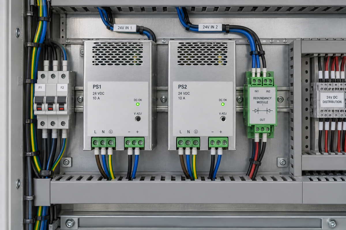
Two power supplies are running, both status indicators are green, and the control cabinet draws less than their combined rating. That sounds reassuring until one supply fails. If the remaining branch cannot carry the full load, the arrangement provides additional capacity but not the redundancy the maintenance team expects.
This distinction is especially important when a cabinet has grown through small modifications. An extra communications device, another bank of sensors and several added interface relays can consume the original reserve without producing an obvious fault. The supply pair remains healthy right up to the moment it is asked to survive a single failure.
The arithmetic that a green indicator cannot answer
Take an illustrative system with two nominal 10 A supplies and a measured continuous demand of 14 A. Even if the arrangement permits them to share that load correctly, losing one supply leaves a demand above the remaining unit’s nominal rating. The total installed rating of 20 A does not make the 14 A load single-fault tolerant.
This is an engineering example, not a design recommendation. Actual allowable load depends on the specific supplies, decoupling equipment, ambient conditions, protection and manufacturer instructions. Any overload or boost capability must be evaluated for its stated duration and conditions; it should not be silently counted as permanent redundant capacity.
For a two-branch arrangement intended to tolerate either supply failing, the practical design question is whether either surviving branch can support the required load throughout the relevant operating conditions. That includes the branch’s upstream supply, conductors, protective devices and downstream decoupling path, not merely the number printed on the power supply.
What a diode module does, and what it cannot create
Phoenix Contact’s TRIO-DIODE 2866514 product data identifies a decoupling module with two 10 A inputs and a 20 A output rating. Its role must be evaluated separately from the capacity of the connected supplies. A decoupling device does not manufacture the missing current when the surviving source is undersized.
When reviewing an existing panel, the QUINT PS/1AC/24DC/10 power-supply reference gives purchasing a specific unit to identify. Preserve the full ordering information from the installed label and verify the applicable documentation before specifying a replacement.
The associated TRIO-DIODE 12-24DC/2X10/1X20 decoupling module belongs on a separate bill-of-materials line. These catalog references are not a preapproved system design. Compatibility, operating limits and protection still require a competent review of the complete arrangement.
Account for loads that are absent during a casual measurement
A single current reading during steady production may miss the worst operating state. Solenoids, communication equipment and other loads can produce different demand during startup, changeover or simultaneous operation. The relevant load case is the one the cabinet must support after the defined failure, not simply the most convenient moment to measure.
Start with the documented load inventory and compare it with the as-built cabinet. Record additions made since commissioning. Where measurements are required, qualified personnel should use an approved method and suitable equipment. Do not pull a live supply or defeat protection merely to see whether the machine continues running.
Temperature is another reason to avoid simple nameplate addition. Review the manufacturer’s derating information, mounting requirements and ventilation conditions. A cabinet that meets its calculated margin in a cool workshop may have a different margin in the plant’s hottest credible operating condition.
Look for the failure that both branches share
Two DC supplies connected to one vulnerable upstream source may not deliver the availability expected by the process owner. Shared protective devices, common terminals or a single downstream distribution point can also remain important failure paths. Redundancy should be described with a stated boundary and failure assumption rather than as an absolute property of the whole cabinet.
Monitoring needs the same precision. Determine whether the control system can distinguish the loss of either source while the common output remains powered. An alarm that appears only after the DC bus collapses gives maintenance little warning that reserve capability has already been lost.
Turn these findings into a load-and-margin record. State the required load, each branch’s allowable capacity under the applicable conditions, the monitoring arrangement and the outstanding assumptions. Review this record whenever a modification adds load. That is more effective than discovering several years later that the original redundancy calculation no longer describes the panel.
Questions buyers and panel maintainers ask
Can two 10 A supplies provide redundant power for a 14 A load?
Not merely because their ratings total 20 A. If either surviving branch cannot support the full required load under the specified conditions, the arrangement does not meet that single-supply-failure objective. The complete design requires review.
Does the diode module’s 20 A output rating prove redundancy?
No. It describes a component rating, not the available capacity after a source fails. Evaluate source capability, decoupling limits, thermal conditions and distribution protection as separate parts of the same power system.
Should we test redundancy by switching off a supply during production?
Do not improvise that test. A controlled test needs an approved procedure, process-risk assessment and qualified personnel. Review the design and load evidence first, then plan verification within an appropriate maintenance window.
What should be included in a replacement enquiry?
Send the full installed part numbers, cabinet load information, ambient conditions, required alarm functions and photographs of identification labels. Make clear whether the request is like-for-like replacement or a redesign intended to restore lost capacity margin.
Buy against the required failure condition
Konmask can review availability for a clearly specified power-supply or decoupling-module requirement. Include the exact designation, quantity, condition expectation and delivery destination. Keep the capacity calculation with your engineering team so a readily available spare does not become an unintended change to the cabinet’s protection or redundancy assumptions.
Image: AI-generated industrial illustration; not a wiring diagram or approved power-system design.
© 2026 Konmask. All rights reserved. Official Website: https://www.konmask.com Inquiry: support@konmask.com | WhatsApp/Tel: +86 19859288691
